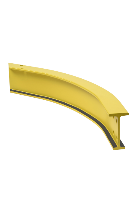
Patented Track Monorail
Move Loads Along Fixed Routes

Patented Track Monorail
Move Loads Along Fixed Routes
Monorail Systems can be used for many different material handling applications … from receipt of raw material to delivery of finished goods. Monorail Systems move loads along fixed routes, using curves, any number of switches and/or transfer sections to alter the route of the load. Carriers for MonoraiI Systems can be either hand propelled or power driven.
Flexibility in Movement
Patented Track monorail systems have the benefits of standard steel beam construction but can also include curves (with radii as small as 18”) in their design to use the overhead space in the most efficient way.
Transferring Loads
With both hand and motor operated latching methods you can easily transfer your load to and from a crane and monorail system via a spur section
Customized Design
Used where loads and building bay-spans are too great to use standard steel beams.
Gimbal Suspension System
The patented track used for monorail systems is suspended by a flexible gimbal suspension system designed to absorb the force applied by the carrier and reduce stress on structural building components.
ELECTRIFICATION AND CONTROLS
Offered in Figure 8 (single conductor) and 810 (double conductor) bar systems, as well as traveling C-Track or tagline festooning systems, there are multiple ways to power your system.
SUPERTRACK
- Operating Flange Width: 2 or 3.33”
- Suspension flange: 2 or 3.33”
- Maximum possible wheel load: 750 lbs. (1500 lbs. per 2-wheel Trolley)
SUPERTRACK GIRDER
- Operating Flange Width: 3.33”
- Suspension flange: 4 to 20”
- Maximum possible wheel load: 2500 lbs. (5000 lbs. per 2-wheel Trolley)
TROJANTRACK GIRDER
- Operating Flange Width: 3.33”
- Suspension flange: 6 to 20”
- Maximum possible wheel load: 3750 lbs. (7500 lbs. per 2-wheel Trolley); 5000 lbs. (10,000 lbs. per 2-wheel trolley) when used as bridge girders without splices or runways without splices
LIGHT RAIL
- Operating Flange Width: 3.25”
- Suspension flange: 5 to 20”
- Maximum possible wheel load: 2500 lbs. (5000 lbs. per 2-wheel Trolley)
HEAVY RAIL
- Operating Flange Width: 3.25”
- Suspension flange: 6 to 20”
- Maximum possible wheel load: 3750 lbs. (7500 lbs. per 2-wheel Trolley); 5000 lbs. (10,000 lbs. per 2-wheel trolley) when used as bridge girders without splices or runways without splices